-
1.What is the relationship between the flow rate, power, and head of a pump
Pump Flow - Often referred to as discharge quantity, pump flow quantifies the volume of water that the pump can transfer in a unit of time. It's a crucial metric displayed on flow meters, symbolized by (Q), measured in liters per second (L/s), cubic meters per second (m³/s), or cubic meters per hour (m³/h). Pump Head - The term 'head' in pumps specifically refers to the vertical distance a fluid is lifted against gravity. Symbolized by (H), typically in meters (m), it consists of two components: the suction head ((H_s)) - the maximum height a pump can lift water from the source, and the discharge head ((H_d)) - the maximum height the pump can push the water to. Thus, pump head is expressed as (H = H_s + H_d). It's worth noting that the manufacturer's specified head does not account for friction losses within the piping system; hence, this must be factored in for accurate application. Pump Power - Defined as the rate at which work is done, power is a measure of energy conversion over time. The standard symbol is (N) and is commonly quantified in units such as kilograms-meters per second (kg·m/s), kilowatts (kW), or horsepower (hp). In the context of motors, power output is often expressed in kW, whereas engines might be rated in hp. Relationships among Parameters For a centrifugal pump (considering two identical impellers with outer diameters (D_1) and (D_2)), the flow rate ((Q)) varies linearly with the diameter, indicated by: [Q_1/Q_2 = D_1/D_2] The relationship between head and outer diameter exhibits a square relationship: [H_1/H_2 = (D_1/D_2)^2] Similarly, the power consumption shows a cubic relationship: [W_1/W_2 = (D_1/D_2)^3] Understanding these relationships ensures informed decision-making in pump selection, optimizing performance and efficiency in various applications.
-
2.What is Main Performance Parameters of Pumps?
Flow Rate and Head The amount of fluid pumped by a pump in a unit of time is called the flow rate, which is typically denoted by the symbol Q for centrifugal pumps. The increase in the energy of the liquid under the action of gravity, obtained by the pump, is called the head and can be represented by the symbol H, with the unit being meters (m). When selecting a water pump, the flow rate and head are the main parameters provided by the design engineers based on the process calculations. These are fixed values. However, in terms of the pump's own performance, the flow rate and head often have a corresponding relationship within a range. These two parameters will influence each other during pump selection. The ideal selection is when the fixed industrial parameters fall within the high-efficiency range of the pump's performance curve. If there are deviations, a comprehensive evaluation of the adverse impacts of the deviations is needed, and the selection result is decided after weighing the pros and cons. Shaft Power and Efficiency The power transmitted by the prime mover to the pump shaft is called the shaft power, which can be represented by the symbol P, with the unit being kilowatts (kW). The power obtained from the fluid by the energy-efficient pump in a unit of time is called the effective power, which can be represented by the symbol Pe. The efficiency of an energy-efficient pump is related to the pump's design level and the level of mechanical processing. The high or low efficiency will directly affect the energy consumption of the pump. Each pump has its own high-efficiency range, and the pump selection should always fall within this high-efficiency range to reduce energy consumption. Rotational Speed The rotational speed of the pump shaft, expressed in revolutions per minute (r/min), is denoted by the symbol N. The rotational speed is usually corresponding to the standard speed of the motor, and can be adjusted to achieve higher energy savings using a variable frequency drive. Cavitation and Net Positive Suction Head Cavitation refers to the phenomenon where the local pressure in the pump drops below the vapor pressure of the liquid, causing the liquid to vaporize and form a gas-liquid flow. When this gas-liquid mixture reaches the high-pressure region, the bubbles are compressed and collapsed, resulting in high water hammer pressures that can cause erosion and damage to the pump materials. Cavitation is directly related to the pump's performance and the design of the suction system. Operating Conditions The physical and chemical properties of the pumped medium, such as characteristics, particle size, particle content, viscosity, density, and vapor pressure, directly affect the pump's structure, materials, and performance. Site Conditions The environmental factors, such as ambient temperature, installation location, atmospheric pressure, relative humidity, atmospheric corrosion, and hazardous area classification, also need to be considered when selecting a pump.
-
3.How to Maintain an Oil Pump?
After a long period of usage, oil pumps require regular maintenance to extend their service life. Here are some steps for normal daily maintenance of an oil pump: 1. Check if there are any looseness in the pump pipes and connections. Rotate the pump by hand to see if it moves smoothly. 2. Add lubricating oil to the rolling bearing body and ensure the oil level is at the bottom line of the oil mark. Replace or refill the grease immediately if necessary. 3. Open the oil plug of the gear oil pump casing and inject or drain the oil. 4. Close the shut-off valve of the outlet line and tighten the pressure gauge at the inlet and outlet. 5. Start the motor and check if it rotates properly. 6. After the thermal oil pump operates normally, slowly open the shut-off valve while monitoring the motor load. 7. Operate the high-temperature thermal oil pump within the flow rate and head range specified on the nameplate to ensure efficient operation and achieve energy-saving and environmental protection. 8. The temperature of the rolling bearing should not exceed 35°C during operation, and the maximum temperature should not exceed 80°C. 9. If any abnormality is found in the pump, stop and check the cause of the fault. 10. Before stopping the pump, close the shut-off valve and pressure gauge, and then stop the motor. 11. Replace the lubricating oil after 100 minutes of operation within one month, and then replace it every 500 minutes. 12. Regularly adjust the packing gland to ensure proper leakage in the packing chamber. A drip leakage is preferred. 13. Regularly check for damage to the shaft sleeve. Replace it immediately if the damage is severe. 14. In cold winter use, after starting the pump, open the water plug under the pump casing to discharge any substances and prevent freezing. 15. When the pump is not in use for a long time, disassemble all the pump parts, wipe off any water, apply grease to rotating and mating parts, and store them properly. 16. Keep each part of the pump and replace with identical parts. When disassembling and inspecting the thermal oil pump, keep each part properly. Pay special attention to explosion-proof parts and avoid damaging or scratching them. If there is any damage, replace it with a new identical part. Do not use substitute materials with lower performance or parts that do not meet the original specifications. During assembly, make sure all parts are installed in their original positions without missing any.
-
4.What are the uses of stainless steel multistage centrifugal pumps?
1. Water treatment: swimming pool ultrafiltration systems, reverse osmosis systems, distillation systems, separators, and water treatment systems. 2. Industrial boosting: process water systems, cleaning systems, high-pressure washing systems, and fire protection systems. 3. Irrigation: for agricultural irrigation, sprinkler irrigation, and drip irrigation. 4. Industrial liquid transportation: cooling and control systems, boiler feedwater and condensate systems, machine tools, and transportation of acid and alkaline media. 5. Water supply: filtration and transportation in waterworks, water supply in waterworks areas, boosting in main pipelines, and boosting in high-rise buildings.
-
5.What is the characteristics of stainless steel multistage centrifugal pumps
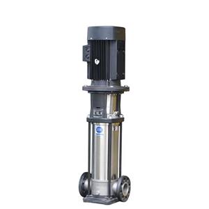
Here are the characteristics of stainless steel multistage centrifugal pumps: 1. The use of excellent hydraulic models and advanced manufacturing technologies has greatly improved the performance and service life of stainless steel multistage centrifugal pumps. 2. The use of mechanical seals made of cemented carbide and fluorine rubber can improve the reliability of stainless steel multistage centrifugal pumps and the temperature of the pumped medium. 3. The overflow part of the stainless steel multistage centrifugal pump is made of stainless steel sheet by stamping and welding, making the pump suitable for mildly corrosive media. 4. The overall structure is compact, small in size, light in weight, low in noise, energy-saving, and easy to maintain. 5. The suction and discharge ports of the stainless steel multistage centrifugal pump are on the same horizontal line of the pump base, which can be directly connected to the pipeline. 6. Standard motors are used, and users can easily match the motors according to their needs. 7. Smart protectors can be equipped according to user requirements to effectively protect the pump from dry running, lack of phase, and overload.


