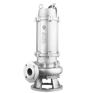
Acceptance method of fire pump
The acceptance of fire pumps is an important part of ensuring the normal operation of the fire protection system. Its acceptance methods mainly include the following aspects:
1. Appearance and specification inspection
Appearance inspection:
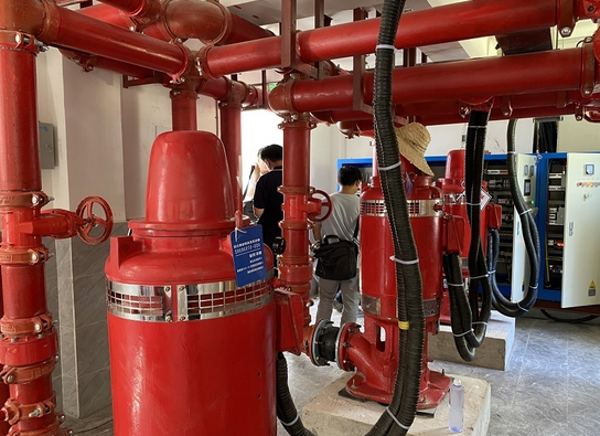
Unpack and inspect the fire pump to ensure that the appearance of the fire pump is intact after delivery from the fire pump manufacturer, and there is no damage, bumps or parts falling off during transportation.
Check whether the specifications, models and quantities of the fire pump and its accessories (such as pressure relief valves, water hammer elimination facilities, check valves, signal valves, etc.) meet the design requirements.
Specification verification:
Verify whether the specifications, models and quantities of the working pump, standby pump, suction pipe, outlet pipe and their accessories meet the design requirements.
Ensure that the control valves on the suction pipe and outlet pipe are locked in the normally open position and are clearly marked.
2. Startup and control inspection
Startup control inspection:
Check whether the start control of the fire pump is set to automatic start mode.
Use the main power supply to start the fire pump and check whether it starts normally.
Disconnect the main power supply and test whether the main and standby power supplies can switch normally.
Verify whether the start-up of the standby pump and the switching function between the main and standby pumps are normal.
Verification of water diversion method:
The fire pump should adopt self-priming water diversion method to ensure that all effective water storage is effectively utilized.
It can be verified by observing whether there is water flowing out of the exhaust hole of the water pump.
3. Performance and operation inspection
Performance parameter inspection:
The performance of the fire pump should meet the flow and pressure requirements of the fire water supply system.
The power of the driver equipped with the fire pump should meet the power requirements for operation at any point on the flow head performance curve of the selected pump.
The flow head performance curve should be a smooth curve without humps and inflection points. The pressure at zero flow should not be greater than 140% of the design working pressure, and should be greater than 120% of the design working pressure.
When the outflow is 150% of the design flow, its outlet pressure should not be lower than 65% of the design working pressure.
Operation inspection:
Ensure that the fire pump runs smoothly without abnormal noise and vibration.
Check whether the local and remote start and stop functions of the fire pump are normal.
4. Pipeline and accessories inspection
Pipeline installation inspection:
Verify whether the installation sequence of the inlet and outlet pipes is correct, especially the installation sequence of accessories on the outlet pipe and suction pipe.
The suction pipe of the fire pump should be arranged to avoid the formation of air pockets, and there should be no air pockets and air leakage on the horizontal pipe section.
Pressure gauge setting:
The maximum range of the pressure gauge of the fire pump outlet pipe should not be less than 2 times its design working pressure, and should not be less than 1.60MPa.
The suction pipe of the fire pump should be equipped with a vacuum gauge, pressure gauge or vacuum pressure gauge. The maximum range of the pressure gauge should be determined according to the specific conditions of the project, but should not be less than 0.70MPa.
Control valve installation:
The suction pipe of the fire pump should be equipped with a rising stem gate valve or a butterfly valve with a self-locking device, but when a concealed stem valve is set, an opening scale and mark should be provided.
When the pipe diameter exceeds DN300, an electric valve should be installed.
5. Other inspections
Inspection of fire pools and water tanks:
The fire pool should be equipped with an on-site water level display device, and a device for displaying the water level of the fire pool should be installed in places such as the fire control center or the duty room.
The effective volume, water discharge, drainage and water level of the high-level fire water tank should meet the requirements of the design documents.
System comprehensive function experiment:
Open each end water test device, water test valve and test fire hydrant in the system respectively, and test whether the functions of the water flow indicator, pressure switch, high-level fire water tank flow switch and other signals meet the design requirements.
6. Acceptance method
Review the project completion drawings: understand the design requirements and system configuration.
On-site inspection: verify the compliance of various indicators through on-site inspection and testing.
Test report: Check the pump performance curve and test report to ensure that the performance of the fire pump meets the design requirements.
