Fire hydrant fire pump structure description
The fire hydrant fire pump unit complies with the standard requirements of GB6245-2006 "Fire Pump" and is mainly composed of a pump body (1), a pump cover (2), an impeller (3), a shaft (4), a sealing ring (5), a shaft sleeve (8), a suspension bearing assembly (12), etc.
The pump body and pump cover of the XBC diesel engine pump are partially split from the rear of the impeller, which is called a rear-open structure. Its advantage is that it is easy to repair. During maintenance, the pump body, suction pipe, discharge pipe, and motor do not move. Only the middle connector (extension part) of the coupling needs to be removed to pull out the rotor component for inspection.
The pump housing (i.e., the pump body and pump cover) constitutes the working room of the pump. The impeller, shaft, and rolling bearing constitute the rotor of the pump. The suspension bearing assembly supports the rotor assembly of the pump, and the rolling bearing bears the radial force and axial force of the pump.
In order to balance the axial force of the pump, most pumps are equipped with sealing rings before and after the impeller, and a balancing hole is provided on the rear cover of the impeller. Some pumps have a smaller axial force, and no sealing ring or balancing hole is provided on the back of the impeller.
The axial sealing ring of the pump consists of a packing gland (9), a packing ring (10), and a packing (11) to prevent air ingress or excessive leakage. If the pump impeller is balanced, the cavity containing the soft packing is connected to the impeller inlet. If the liquid at the impeller inlet is in a vacuum state, air can easily enter along the surface of the shaft sleeve. Therefore, a packing ring is installed in the packing cavity through the small hole on the pump cover to seal the pressure water in the pump cavity to the packing ring. If the pump impeller is unbalanced, since the liquid pressure behind the impeller is greater than the atmospheric pressure, there is no leakage problem and the packing ring can be omitted.
To prevent shaft wear, a sleeve is installed at the part where the shaft passes through the packing cavity, and an O-ring is installed between the sleeve and the shaft to prevent air ingress or water leakage along the mating surface.
The pump is driven by an extended flexible coupling connected to the motor. The rotation direction of the pump is clockwise when viewed from the drive end.
The pump inlet and outlet flanges are designed according to the 1.6MPa pressure to facilitate pipeline matching.
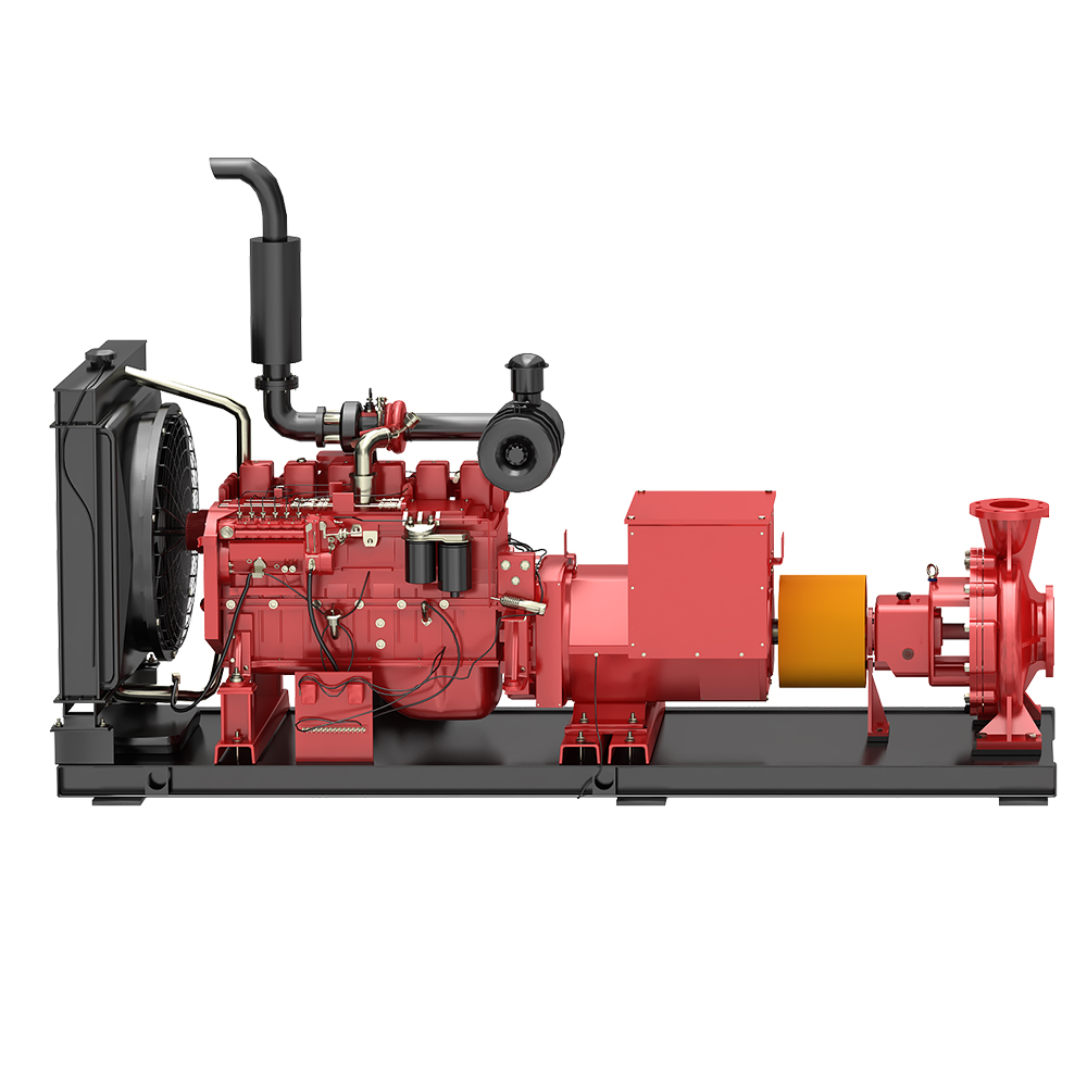
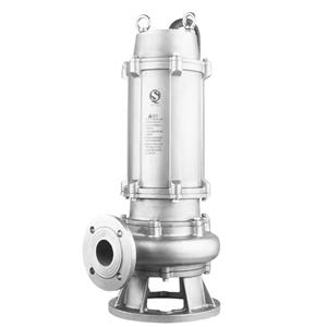
Diesel engine fire pump rendering: