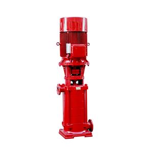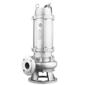
Hydrant Firefighting Pump

- Gaotian
- Shanghai
- 15days
- 1500
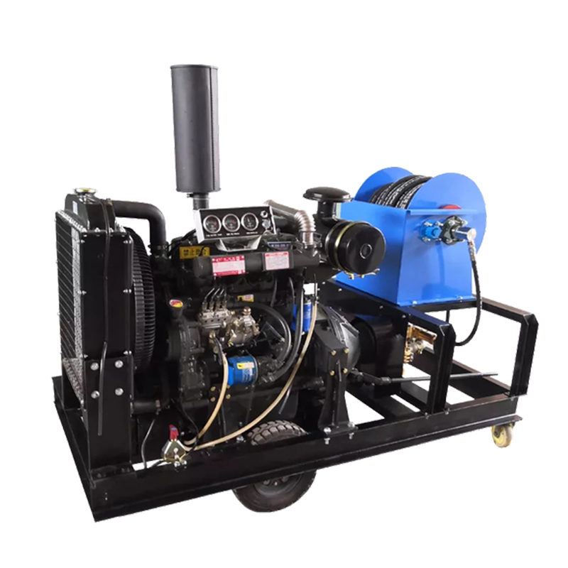
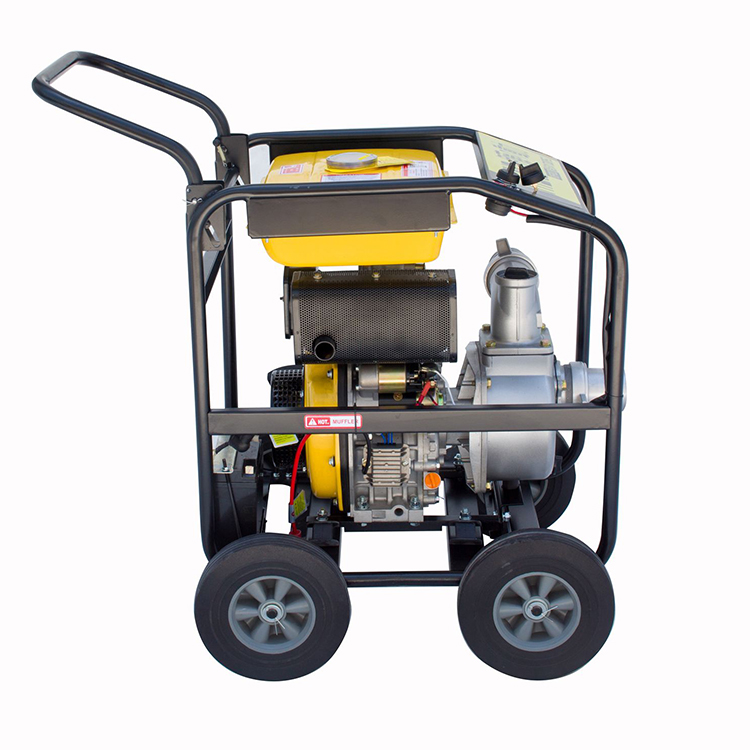
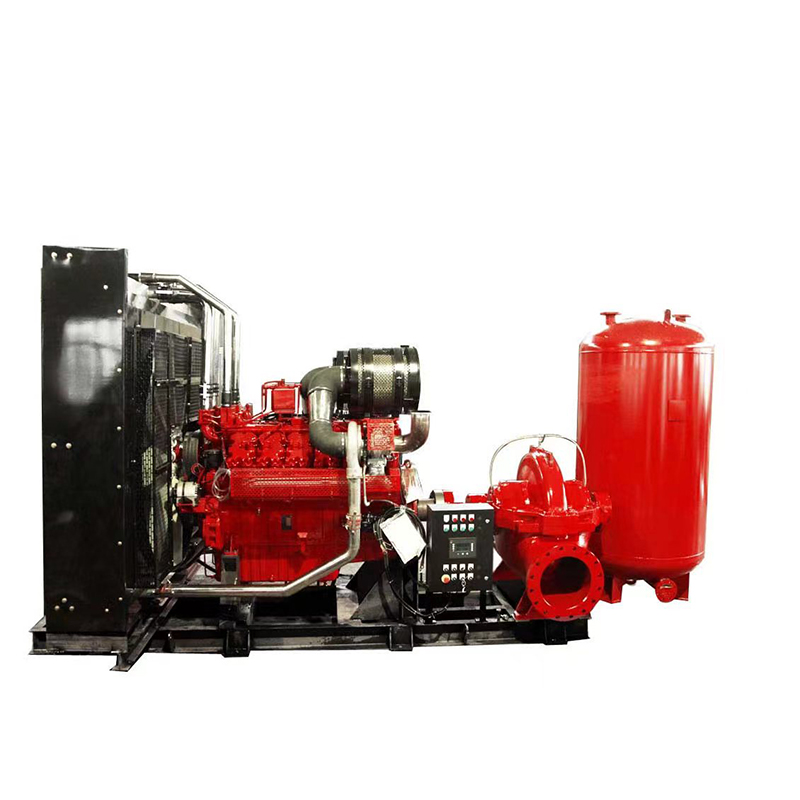
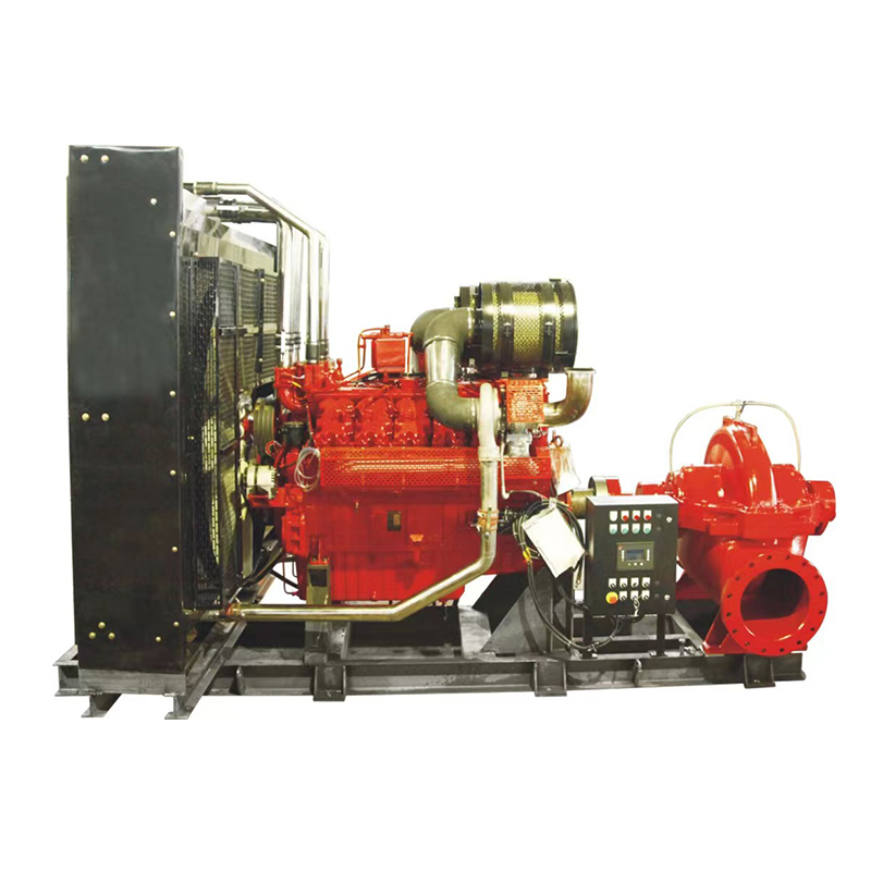
Diesel engine fire pumps, as a type of fixed fire extinguishing equipment, have been widely used in fire water supply, especially in situations where there is no power source or the power supply (utility power) is abnormal. They are suitable for unattended emergency water supply systems, and the products have the characteristics of good technology, high degree of automation, superior performance, complete protection functions, reasonable structure, easy installation, and high cost-effectiveness. When the factory experiences a sudden power outage, the pump set automatically starts to supplement the network pressure.
Main Features of Diesel Engine Fire Pump
1. The electric pump is the primary fire pump and can automatically start according to fire conditions.
2. Equipped with a stabilizing pump to maintain constant network pressure.
3. The diesel engine pump serves as a backup fire pump and automatically starts in case of a power outage for firefighting.
4. The diesel engine pump starts when the electric pump malfunctions.
Hydrant Firefighting PumpApplications
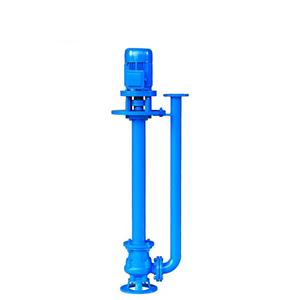
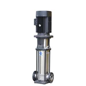
Hydrant Firefighting Pump sets are mainly used for boosting water supply in fire system pipelines. They can also be applied in industrial and urban water supply and drainage, high-rise building water boosting, long-distance water supply, heating, bathrooms, boiler hot and cold water circulation, air conditioning and refrigeration system water supply, and equipment matching.
Structural Description of Hydrant Firefighting Pump
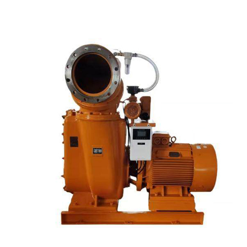
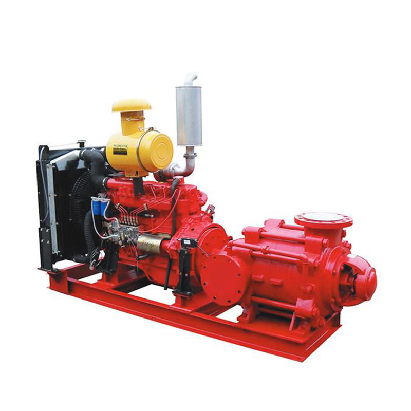
Hydrant Firefighting Pump sets comply with the standard requirements of GB6245-2006 "Fire Pumps" and mainly consist of pump body (1), pump cover (2), impeller (3), shaft (4), sealing ring (5), shaft sleeve (8), and suspension bearing components (12), etc.
Hydrant Firefighting Pump body and pump cover of the XBC type diesel engine pump are partially split from the back of the impeller, known as the rear-opening structure. Its advantage lies in convenient maintenance, where during maintenance, the pump body, suction pipe, discharge pipe, and motor remain stationary, and only the intermediate connector of the coupling (extended) needs to be removed to withdraw the rotor components for inspection.
The pump casing (i.e., pump body and pump cover) constitutes the working chamber of the pump. The impeller, shaft, and rolling bearings form the rotor of the pump. Suspension bearing components support the rotor components of the pump, while rolling bearings withstand the radial and axial forces of the pump.
To balance the axial forces of the pump, most pumps are equipped with sealing rings both before and after the impeller, with balancing holes on the impeller back cover. Some pumps have small axial forces, so no sealing rings or balancing holes are provided on the impeller back.
The axial sealing ring of the pump is composed of packing gland (9), packing ring (10), and packing (11) to prevent air intake or excessive leakage. If the pump impeller is balanced, the cavity filled with soft packing communicates with the impeller inlet. If the liquid at the impeller inlet is in a vacuum state, it is easy for air to enter along the shaft sleeve surface. Therefore, packing rings are installed in the packing cavity through small holes on the pump cover to seal the pressure water in the pump chamber to the packing ring. If the pump impeller is unbalanced, since the liquid pressure at the back of the impeller is greater than atmospheric pressure, there is no air leakage issue, and packing rings may not be installed.
To prevent shaft wear, shaft sleeves are installed at the portion where the shaft passes through the packing cavity. O-ring seals are installed between the shaft sleeve and the shaft to prevent air intake or water leakage along the mating surface.
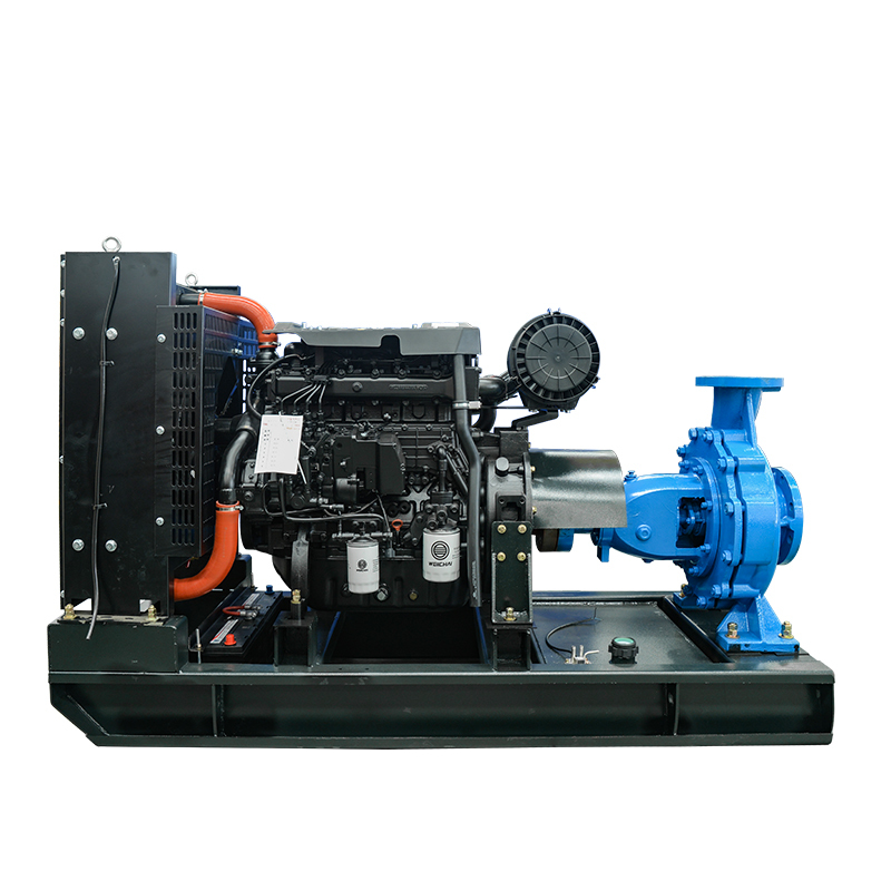
The pump is driven by an extended flexible coupling connected to the motor, and the rotation direction of the pump, as viewed from the drive end, is clockwise.
The inlet and outlet flanges of the pump are designed for 1.6 MPa pressure, facilitating pipeline matching.
Diesel Engine Fire Pump Rendering